





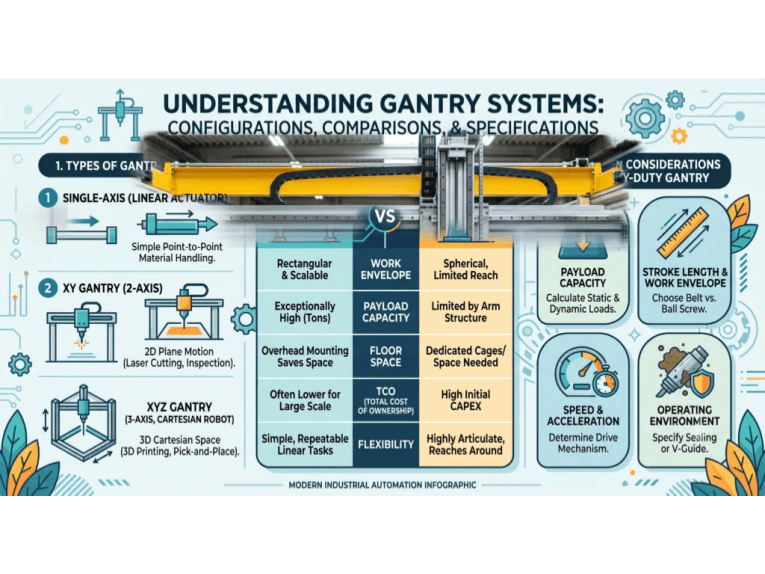
What is a Gantry System and Its Core Components
A gantry system is essentially a cartesian robot featuring a multi-axis mechanical framework that moves tools or payloads with high precision over a large work area. Its Key components include rigid linear rails and frames, bearings or slides for smooth motion, motors and drive mechanisms for movement, and software and hardware control systems.
Gantry systems gantry are useful in heavy automation and precision engineering activities such as transporting heavy parts, layer by layer in 3D printing, or even printing in a micrometer range.Blade propelled vehicles, as opposed to robotic arms, enable much more intricate industrial work. Their ability to function within linear, computer controlled, guided settings allows for extreme accuracy, high workspace availability, and significant payload capacity. As such, they are required in a range of industries, from automotive to electronics.
Theoretical Concepts of Gantry Systems
Gantry systems are a form of linear robotic platform designed to move objects or tooling in orthogonal directions. They consist of an overhead frame or bridge that spans a work area, with a carriage (or trolley) that traverses along one or more axes. This configuration is essentially a Cartesian coordinate robot that can position a payload at any X-Y-Z coordinate within its working envelope. Because of this design, gantry robots are sometimes simply called Cartesian robots or linear robots.
1. Role in Automation
Gantry systems provide reliable and repeatable positioning for automated tasks like pick-and-place, assembly, and inspection, reducing human fatigue and enhancing consistency. Their large workspaces and high load capacities enable them to service entire assembly lines, surpassing traditional robotic arms in large-scale operations. They are valued for their speed and precision, making them ideal for broad automation tasks.
2. Role in Precision Engineering
Gantry systems excel in precision engineering due to their rigid linear motion, achieving micrometer-level accuracy crucial for electronics and semiconductor manufacturing. This accuracy is vital for tasks like CNC machining, 3D printing, and metrology, where precise positioning is paramount for quality and reliability.
3. Comparison with Articulated Robots
Another theoretical aspect is the difference in kinematics compared to articulated robots. Gantry robots, with their linear axes, offer simpler kinematics compared to 6-axis robotic arms, which have complex rotary joint movements. This results in easier programming and control, especially for straightforward or planar motions. The constrained linear motion of gantries also provides inherent repeatability, reducing errors from flex and backlash.
Core Components and Mechanics of Gantry Systems
To understand how gantry systems achieve their performance, let’s break down their core components and mechanics. A gantry’s design is modular, comprising several key subsystems that work in concert:
1. Linear Frame and Rails
Linear rails are the backbone of a gantry robot, providing the tracks along which the moving elements travel. They are typically long, straight tracks made of hardened steel or aluminum, precisely machined to ensure minimal friction and deflection.
Common rail designs include profile rails (rectangular cross-section rails with matching bearing blocks) and round shaft rails.
- Profiled linear rails offer high precision and load capacity by using machined tracks and recirculating ball bearings,
- Round rails are simpler and often used for lighter loads.
In some gantries, two parallel rails are used for an axis to increase stability (for example, dual X-axis rails supporting a bridge). These rails must be stiff and aligned perfectly straight, as they define the path of motion. Any deviation in the rails would directly translate to positioning errors.
2. Frame and Gantry Bridge
The frame is the structural framework that holds the rails and other components. Many gantry systems have a bridge or gantry beam that spans between two side supports (like the gantry crane analogy). This bridge carries the Y-axis and Z-axis components.
In a true gantry, both ends of the bridge are supported and move along the X-axis rails. This dual-support design enhances rigidity and allows heavier payloads and longer travel without sagging.
Frames are usually made from steel or aluminum extrusions to provide a stable, vibration-resistant base. The mechanical structure must withstand not only the static weight of payloads but also dynamic forces from acceleration and deceleration.
3. Bearings and Linear Slides
Mounted on the rails are bearing blocks or linear slides that allow the gantry’s moving parts to glide smoothly. These bearings minimize friction between the stationary rails and the moving carriage. There are a few common types:
- Recirculating Ball Bearings: Low-friction, high-precision, and load-bearing; ideal for smooth, accurate motion in precision gantries.
- Roller Bearings: High load capacity and stiffness; suitable for heavy-duty applications due to their increased contact area.
- Plain Sliding Bearings: Low-cost, robust against dirt, and self-lubricating; used in low-speed, low-precision gantries due to higher friction.
Proper selection of bearings is crucial. The bearing blocks must support not just the payload but also the forces of acceleration (which can be many times the payload weight). They also maintain alignment – poor alignment can cause binding or uneven wear.
4. Actuators: Motors and Drive Mechanisms
Movement in each axis of a gantry is driven by an actuator. The choice of motor and drive mechanism directly affects the system’s speed, force, and precision.
- Stepper Motors: Common in cost-sensitive applications like 3D printers and DIY CNC machines. Stepper motors rotate in discrete steps, enabling open-loop position control. While simple and precise at lower speeds, they can lose synchronization under high loads.
- Servo Motors: Used for high-performance gantry systems requiring fast, accurate motion. Paired with encoders and closed-loop controllers, they provide real-time feedback and error correction. These are ideal for industrial robots needing high throughput and precision, especially with variable loads.
- Linear Motors: Found in advanced gantry systems, eliminating mechanical transmissions for direct linear motion. They provide smooth motion, high speeds, and exceptional precision due to the absence of backlash. Linear motors are used in high-end applications like semiconductor manufacturing, where extreme accuracy is crucial.
5. Drive Mechanics
The motor’s rotation usually needs to translate into linear travel. Common mechanisms include:
- Ball Screw Drives: Ball screws, driven by a motor, translate rotary motion to linear carriage movement, offering high precision and thrust essential for applications like machine tools. Their minimal backlash, particularly with preloaded nuts, enables micron-level repeatability. However, length constraints to prevent sagging and slower speeds on long axes are limitations.
- Belt Drives: Belt drives, utilizing a motor-driven toothed belt, enable long travel and high speeds, common in packaging and large-area 3D printers, though they offer lower positioning accuracy due to elasticity and are best for light-to-medium loads.
- Rack and Pinion Drives: Rack and pinion drives, using a motor-driven pinion engaging a linear rack, handle heavy loads and unlimited lengths, suitable for large CNC routers, offering good precision with high-quality components despite potential backlash.
6. Control Systems and Software
The “brain” of a gantry system is its control system – typically a motion controller or PLC (Programmable Logic Controller) combined with software that plans and coordinates movement. The control system reads the desired positions and feeds commands to the motors (and monitors feedback from encoders, if present) to execute smooth, coordinated motion along all axes.
Key elements of gantry control include:
- Motion Controller / PLC: This hardware coordinates multi-axis movements. In advanced setups, a dedicated motion controller or an industrial PLC with motion control functions calculates the motor trajectories. It ensures that if, for instance, the X and Y axes need to move simultaneously to draw a diagonal line, they do so at the correct relative speeds.
- Feedback Sensors: Encoders on motors (or linear scales on axes) provide real-time position feedback to correct any error between the commanded position and actual position. Some gantry systems use high-resolution linear encoders for micron-level precision. For example, a high-end PCB assembly gantry might use linear glass scales to guarantee placement accuracy of components on a circuit board.
- Software and Programming: On the software side, gantry systems can be programmed using specialized motion software or G-code. Modern software allows users to plan complex paths, adjust speeds (feeds) and accelerations, and even integrate machine vision or sensors. Features like trajectory planning ensure the gantry moves along smooth curves rather than jerky axis-by-axis motions. The software typically provides a user interface for operators to input parameters, run jobs, and monitor status.
Post time: Oct-19-2026