





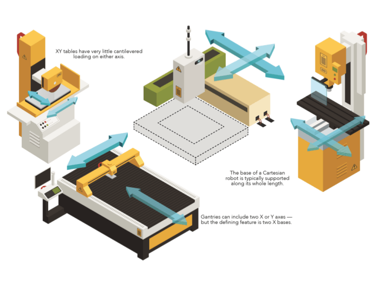
There are many ways to build linear systems for motion in the X, Y, and/or Z directions — also called Cartesian coordinates. Industry terms for these systems depend on how the axes are assembled, where the load is positioned, and (to some extent) the type of use for which the system was designed. In many industrial applications, Cartesian and gantry-style robots are prevalent … but in precision applications, XY tables are often the better choice due to their compact rigid structure and very high travel and positioning accuracies.
Cartesian systems consist of two or three axes — X-Y or X-Z or X-Y-Z. They often incorporate an end effector with a rotational component for orienting the load or workpiece, but they always provide linear motion in at least two of the three Cartesian coordinates.
Cartesian systems can include two axes (X and Y) or three axes (X, Y, and Z). When a Cartesian system is used, the load is usually cantilevered from the outermost axis (Y or Z). For example, in an X-Y gantry the load is mounted to the Y axis either to the end of the axis or at a distance from the axis … creating a moment arm on the Y axis. This can limit load capacity, particularly when the outermost axis has a very long stroke, creating a large moment on the lower, supporting axes. They’re used in a wide range of applications with maximum strokes on each axis typically one meter or less. The most common of these applications include pick-and-place, dispensing, and assembly.
To address the issue of outer axes causing a moment load on the inner axes, gantry systems use two X axes, and in some cases, two Y and two Z axes. Gantries almost always have three axes — X, Y and Z. The load on a gantry system is located within the gantry’s footprint and the gantry is mounted over the working area. However, for parts that cannot be handled from above, gantries can be configured to work from below.
Gantry systems are used in applications with long strokes (greater than one meter) and can transport very heavy payloads that are not suitable for a cantilevered design. One of the most common uses for gantry systems is overhead transport, such as moving large automotive components from one station to another in an assembly operation.
XY tables are like XY Cartesian systems in that they have two axes (X and Y, as their name implies) mounted on top of each other, and typically have strokes of one meter or less. But the key difference between XY Cartesian systems and XY tables lies in how the load is positioned. Instead of being cantilevered, as in a Cartesian system, the load on an XY table is almost always centered on the Y axis, with no significant moment created on the Y axis by the load.
This is where the principle of how the system is used helps distinguish between the various types of multi-axis systems. XY tables generally work only within their own footprint, meaning the load does not extend beyond the Y axis. This makes them best suited for applications where a load needs to be positioned in the horizontal plane (X-Y). A typical example is a semiconductor wafer being positioned for inspection, or a part being positioned for a machining operation to take place. Designs called open-frame or open aperture have a clear opening through the center of the table. This allows them to be used in applications where light or objects need to pass through, such as back-lit inspection applications and insertion processes.
Because XY tables are primarily used for very high precision applications, the guideway of choice is crossed roller slides, which provide extremely smooth and flat travel. Drive mechanisms are typically ballscrew or linear motor, although very fine pitch lead screws are also common.
The base (X) axis of a Cartesian robot is generally supported along its entire length, but the Y or Z axis is cantilevered. A gantry configuration can include two Y and/or two Z axes, for additional load capacity and stiffness, but the defining feature of a gantry robot is its two base (X) axes. Unlike Cartesian systems, which have significant cantilevered loads, XY tables have very little cantilevered loading on either axis.
The special case of stages
Positioning stages and rotary tables are leading the migration to integrated designs in motion applications. Just consider how fiber optic, test and measurement, and semiconductor applications such as assembly setups all use precision stages and tables to boost throughput and quality. More specifically, the manufacture of flat-panel displays has spurred ever-larger motion-stage formats with linear-motor actuation and air-bearing load carrying. Elsewhere, belt-driven stages satisfy the need for long strokes but avoid ballscrew support challenges and the cost of linear motors.
Another growth industry using positioning stages is additive manufacturing. Here, ever-improving materials and layup techniques demand new stages at all performance levels. Many basic maker-level machines use stages with synchronous belt-driven axes. More demanding applications (such as research and prototyping, medical, and small-batch manufacturing) commonly use positioning stages with motor-driven ballscrews to coordinate motion. In the same way, medical and life-research applications make use of ultra-precision stages that deliver performance motion profiles impossible a decade ago. Here, piezomotors, miniature linear supports, and coarse-and-fine tandem actuators are increasingly common options.
Pre-engineered positioning stages dominate packaging, as this industry often forces integrators to satisfy design schedules that bar design and set up of multi-axis functions in house. Likewise, the machine-tool industry is making more use of custom-built positioning stages—in laser-cutting and similar machines, for example. These and the stages for CNC applications are increasingly customized to specific motion tasks. That helps them deliver on dynamic parameters at lower cost and without the hassle of reformatting or retrofitting stock setups. Enabling this newer approach are proliferating software tools that let OEMs and end users manipulate initial design iterations within virtual environments that have accurate models of real-world stage components.
Assembly is different. Here, semi-custom Cartesian stages excel for pick-and-place and inspection via machine vision. More typical in these setups are traditional rotary motors paired with rotary-to-linear devices (ballscrews, for example) and controllers that compensate for system dynamics to get accuracy to a few micrometers or better.
Automotive applications widely vary. For example, the large scale of sheet metal and body-assembly tasks present unique challenges that, in some cases, only overhead stages (or those with rack-and-pinion sets) satisfy. At the opposite end of the spectrum, stages that carry inspection instrumentation to detect part features on a nanometer scale often take the form of direct-drive axis assemblies driven by a precision controller that even corrects for environmental fluctuations.
Post time: Oct-09-2026