Linear encoders boost accuracy by correcting errors downstream of mechanical linkages.
Linear encoders track axis position without intermediate mechanical elements. The encoders even measure transfer errors from mechanical linkages (such as rotary-to-linear mechanical devices), which helps controls correct for errors originating from the machine. Thus, this feedback lets controls account for all mechanics in position-control loops.
How photoelectric scanning works in encoders
Many precision linear encoders work by optical or photoelectric scanning. In short, a read head tracks periodic graduations just a few micrometers wide and outputs signals with small signal periods. The measuring standard is usually glass or (for large measuring lengths) steel bearing periodic graduations—marks on the carrier substrate. It’s a contact-free mode of position tracking.
Used with incremental grating periods between 4 and 40 μm, PRC (absolute) code image-scanning linear encoders work with light-signal generation. Two gratings (on the scale and scanning reticle) move relative to each other. The scanning reticle’s material is transparent, but the scale’s material can be transparent or reflective. When the two pass each other, incident light modulates. If gaps in the gratings align, light passes through. If the lines of one grating coincide with gaps of the other, it blocks the light. Photovoltaic cells convert the variations in light intensity into electrical signals with a sinusoidal form.
Another option for graduations with grating periods of 8 μm and smaller is interferential scanning. This linear-encoder mode of operation leverages diffraction and light interference. A step grating serves as the measuring standard, complete with lines 0.2 μm high on a reflective surface. In front of that is a scanning reticle—transparent grating with a period that matches that of the scale. When a light wave passes through the reticle, it diffracts into three partial waves with -1, 0, and 1 orders of roughly equal intensity. The scale diffracts the waves so luminous intensity concentrates in diffraction orders 1 and -1. These waves meet again at the reticle’s phase grating where they diffract once more and interfere. This makes three waves that leave the scanning reticle at different angles. Photovoltaic cells then convert the alternating light intensity into electrical-signal output.
In interferential scanning, relative motion between reticle and scale causes the diffracted wave fronts to undergo a phase shift. When the grating moves by one period, the wave front of the first order moves one wavelength in the positive direction, and the wavelength of diffraction order -1 moves one wavelength in the negative. The two waves interfere with each other when exiting the grating, so shift relative to each other by two wavelengths (for two signal periods from a move of just one grating period).
Two encoder-scanning variations
Some linear encoders make absolute measurements, so the position value is always available when the machine is on, and electronics can reference it at any time. There’s no need to move axes to a reference. The scale graduation has a serial absolute code structure and a separate incremental track is interpolated for the position value while concurrently generating an optional incremental signal.
In contrast, linear encoders working off incremental measuring use graduations with periodic grating, and the encoders count individual increments (measuring steps) from some origin to get position. Because this setup uses an absolute reference to ascertain positions, scale tapes for these setups come with a second track with a reference mark.
Absolute scale position established by the reference mark is gated with exactly one signal period. So the read head must locate and scan a reference mark to establish an absolute reference or to find the last selected datum (which sometimes requires long-stroke reference runs).
Linear encoder iterations
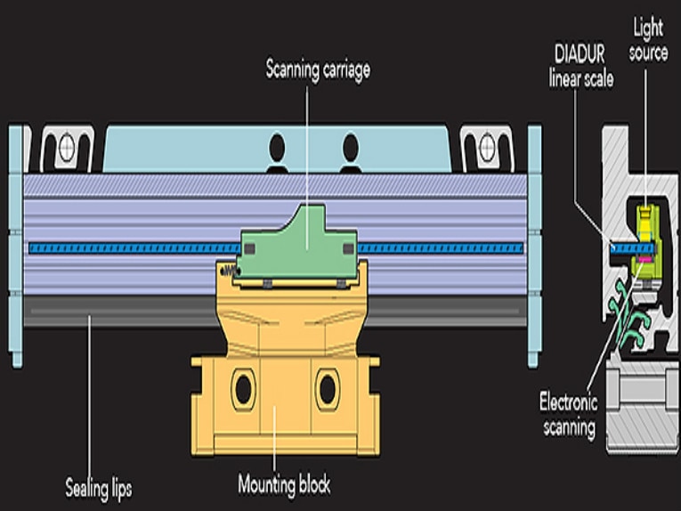
One challenge in linear encoder integration is that the devices operate right at the motion axis, so are exposed to the machine environment. For this reason, some linear encoders are sealed. An aluminum housing protects the scale, scanning carriage and its guideway from chips, dust and fluids, and downward-oriented elastic lips seal the housing. Here, the scanning carriage travels along the scale on a low-friction guide. A coupling connects the scanning carriage with the mounting block and compensates for misalignment between the scale and machine guideways. In most cases, lateral and axial offsets of ±0.2 to ±0.3 mm between the scale and mounting block are allowable.
Case in point: Machine-tool application
Productivity and accuracy are paramount to myriad applications, but changing operating conditions often make those design objectives challenging. Consider machine tools. The manufacture of parts has moved to increasingly small batch sizes, so setups must maintain accuracy under various loads and strokes. Perhaps most demanding is the machining of aerospace parts, which needs maximum cutting capacity for roughing processes and then maximum precision for subsequent finishing processes.
More specifically, milling quality molds needs fast material removal and high surface quality after finishing. At the same time, only fast contouring feed rates let machines output parts with minimum distances between paths within acceptable machining times. But especially with small production batches, it’s almost impossible to maintain thermally stable conditions. That’s because changes between drilling, roughing and finishing operations contribute to fluctuations in machine-tool temperatures.
What’s more, workpiece accuracy is key to making production orders profitable. During the roughing operations, milling rates increase to 80% or better; values below 10% are common for finishing.
The problem is that increasingly high accelerations and feed rates cause heating in the subcomponents of machines’ linear feed drives, particularly those that use rotary-motor-driven ballscrews. So here, position measurement is essential to stabilize machine-tool corrections for thermal behavior.
Ways to address thermal instability issues
Active cooling, symmetrical machine structures, and temperature measurements and corrections are already common ways to address thermally induced accuracy changes. Yet another approach is to correct for a particularly common mode of thermal drift—that of rotary-motor-driven feed axes incorporating recirculating ballscrews. Here, temperatures along the ballscrew can rapidly change with feed rates and moving forces. Resulting changes in length (typically 100 μm/m within 20 minutes) can cause significant workpiece flaws. Two options here are to measure the numerically controlled feed axis through the ballscrew with a rotary encoder or through a linear encoder.
The former setup uses a rotary encoder to determine slide position from the feed-screw pitch. So, the drive must transfer large forces and act as a linkage in the measuring system—providing highly accurate values and reliably reproduce screw pitch. But the position-control loop only accounts for rotary-encoder behavior. Because it can’t compensate for changes in the driving mechanics due to wear or temperature, this is actually semi-closed-loop operation. Drive positioning errors become unavoidable and degrade workpiece quality.
In contrast, a linear encoder measures slide position and includes complete feed mechanics in the position control loop (for truly closed-loop operation). Play and inaccuracies in the machine’s transfer elements have no influence on position-measurement accuracy. So, accuracy depends almost solely on the precision and installation of the linear encoder. One side note here: Direct encoder measurement can also improve measurements of rotary-axis motion. Traditional setups use speed-reduction mechanisms that connect to a rotary encoder on the motor, but high-accuracy angle encoders deliver better accuracy and reproducibility.
Ways that ballscrew design addresses heat
Three other approaches to address ballscrew heat have their own limitations.
1. Some ballscrews prevent internal heating (and heating of surrounding machine parts) with hollow cores for coolant circulation. But even these exhibit thermal expansion, and a temperature increase of only 1 K causes positioning errors to 10 μm/m. That’s significant because common cooling systems can’t hold temperature variations to less than 1 K.
2. Sometimes engineers model thermal expansion of the ballscrew in the controls. But because the temperature profile is difficult to measure during operation and is influenced by wear of the recirculating ball nut, feed rate, cutting forces, traverse range used, and other factors, this method can cause considerable residual errors (to 50 μm/m).
3. Some ballscrews get fixed bearings at both ends to boost the rigidity of the drive mechanics. But even extra rigid bearings cannot prevent expansion from local heat generation. Resulting forces are considerable, and deform even the most rigid bearing configurations—sometimes even causing structural distortions in machine geometry. Mechanical tension also changes the friction behavior of the drive, degrading the machine’s contouring accuracy. What’s more, semi-closed-loop operation can’t compensate the effects of bearing-preload changes due to wear or elastic drive-mechanic deformation.
Post time: Oct-12-2020


