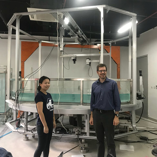
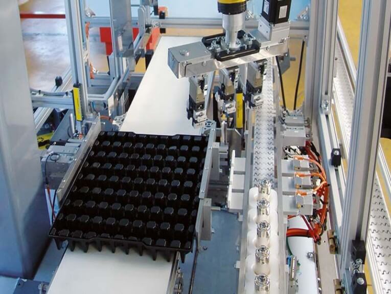
Pick-and-place application, such as laboratory use, benefit from cantilevered construction because components are easily accessible. Gantry robots are Cartesian coordinate robots with horizontal members supported at both ends; physically, they are similar to gantry cranes, which are not necessarily robots. Gantry robots are often gigantic and capable of carrying heavy loads.
Difference between Gantry and Cartesian robots
A Cartesian robot has one linear actuator on each axis, whereas, a gantry robot has two bases (X) axes and a second (Y) axis that spans them. This design stops the 2nd axis from being cantilevered (more on that later) and makes for even longer stroke lengths in gantries and greater payload compare to Cartesian robot.
The most-common of Cartesian-robots use the dual guided design because it provides more excellent protection for overhung (moment) loads; however, axes with dual linear guides have a more foot print than axes with single one, in comparison dual-guide systems generally short (in the vertical direction) and may eliminate interaction with other areas of the machine. The argument is that the sort of axes you chose has an impact not just on the Cartesian system’s efficiency but also on the overall footprint.
Cartesian Robot Actuators
If a Cartesian mechanism is the best choice, the following design factor usually is the actuator control unit, which may be a bolt, screw, or pneumatic-driven system. Linear actuators are generally available with a single or dual linear guide depending on the drive system.
Cable Control and Management
Cable control is another essential feature of this robot design that is often ignored in the early stages (or merely postponed to later stages of the plan). For control, air (for pneumatic axes), encoder input (for servo-driven Cartesian), sensor, and other electrical apparatuses, each axis involves several cables.
When systems and components are connected through the Industrial Internet of Things (IIoT), the methods and tools used to link them become much more critical and both of these tubes, wires, and connectors must be routed appropriately and maintained to avoid premature fatigue from undue flexing or disruption from interference with other device components.
The type and quantity of cables required, as well as the sophistication of cable management, are all determined by the kind of control and network protocol. Note that the cable management system’s cable carrier, trays, or housings will affect the total system’s measurements, so make sure there’s no conflict with the cabling system and the rest of the robotic components.
Cartesian Robot Controls
Cartesian robots are the preferred method for making point-to-point movements, but they can also do complex interpolated and contoured motion. The type of motion needed will specify the best control device, networking protocol, HMI, and other motion components for the system.
While these components are located independently from the robot’s axes, for the most part, they will have an impact on the motors, wires, and other on-axis electrical components needed. These on-axis elements would influence the first two design considerations, positioning and cable control.
As a result, the design process falls full circle, stressing the importance of constructing a Cartesian robot as an interconnected electromechanical device rather than a set of mechanical parts attached to electrical hardware and software.
Cartesian Robot Work Envelope
Various robot configurations produce distinct working envelope shapes. This working envelope is crucial when choosing a Robot for a specific application because it specifies the manipulator and end effector’s work area. For a multitude of purposes, care should be practiced when studying a Robot’s work envelope:
1. The working envelope is the amount of work that can be approach by a point at the end of the Robotic arm, which is typically the middle of the end-effectors mounting arrangments. It does not have any instruments or workpieces owned by the end-effector.
2. There are sometimes locations inside the operating envelope that the Robot arm cannot enter. Dead zones are the name given to specific regions.
The maximum payload capability cited is only achievable at such arm lengths, which may or may not reach maximum reach.
3. The Cartesian configuration’s operating envelope is a rectangular prism. Inside the working envelope, there are no dead zones, and the Robot can manipulate the full payload over the entire working volume.
Post time: Jan-03-2023


